Import PSD - Tutorial
April 8th, 2024
This guide has the goal to explain through incremental examples the tag system used by the Spine Import PSD feature. Learning this mechanisms let you unlock the full power of the Import PSD feature. To simplify this long tutorial, we provide a PSD file containing all the assets needed. The file containes a folder for each step we are going to do. You can the PSD file here.
Layers to attachments
Let's start our example with a simple character splitted into pieces.
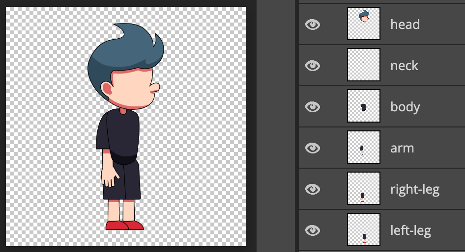
In the first folder, we have Spineboy separated in six pieces. When we import this PSD into Spine with default options, we have the following situation in the three and in the viewport.

For each PSD layer, Spine creates an attachment inside a slot with the same name in the root bone. In the viewport, we can see Spineboy centered and with the surrounding whitespace removed.
Whitespaces are removed because Trim whitespace in the Import PSD dialog is checked by default. For example, if we look at the neck layer into out PSD file, that is a 24x33 pixels image into a 800x800 pixels canvas. It results to be a 26x35 pixels attachment into Spine.
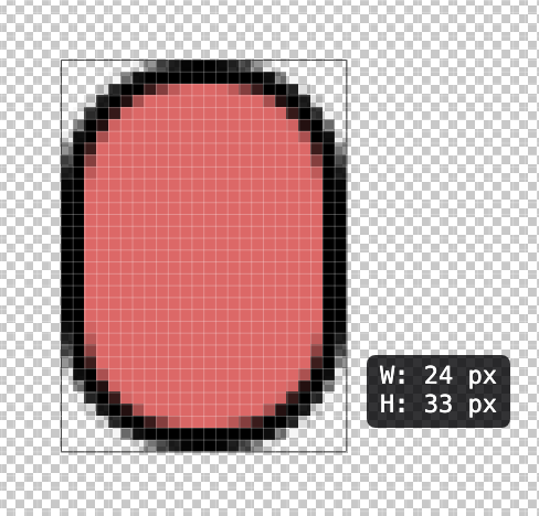

Whitespaces are removed because Trim whitespace in the Import PSD dialog is checked by default. However, there is still a 1 pixel thin transparent border around our neck because the default value for the Padding import option is 1 pixel. This is why the attachment has a 26x35 pixels size into Spine rathern than 24x33. We can use the Padding slider to control the size of this transparent border.

Using a transparent border can avoid aliasing artifacts for opaque pixels along the image border.
Spineboy is centered in the viewport because when no origins are set in the PSD file, Spine uses the PSD canvas center as origin. This is our case becuse the provided PSD has no guides set.
Ignoring layers
Now, let's add a grey background to our PSD. Adding a background helps to visualize the character as if it was in a scene. This is a typical situation where we might want to have a layer in your PSD, but we don't want to impot it into Spine. There are two ways of getting this result. You can check the Ignore hidden layers options, that is unchecked by default, and hide your layer in the PSD.

However, if you prefer to keep the layer visible in your graphic editor, you can instead use the [ignore] tag on your layer. Let's add the background with the [ignore] tag.

Importing the new version of our PSD will result in the very same result as the previous step. However, in our PSD we can work with a convenient background.
The [ignore] tag works also on folders and all children (and children of children) will inherit this property.
Using folders to organize your file
Organizing well our PSD file and giving meaningful names helps in finding layers in our graphic software. In our example, we want to add the left-leg and the right-leg in a group named legs. Since the term leg is already into the group, we can rename our legs just left and right.

However, importing this PSD into Spine will result in losing the information about left and right being legs. As in our graphic software, we want to keep having meaningful names for our attachments. We can use the [folder] tag to keep the folder name into our attachments. Let's add [folder] to the legs group.

Now, when we import the PSD into Spine, the attachments within the legs [folder] group will have the value of the [folder] tag prepended to the layer name and separated by a /.

Moreover, the image files of our attachment are saved into a shapes folder if the output image folder.

The [folder] tag works also on layers. Furthermore, its effect is cumulative. If multiple groups have the [folder] tag, the attachment names and the image files will respect the [folder] tags hierarchy and multiple folders will be nested into the output image folder. For example, if we add an additional [folder:limbs] group that contains the shapes [folder], like this:

The result will be the following:


We don't really need the [folder:limbs] group. We can get rid of it and go to the next paragraph.
Multiple layers in the same slot
Right now all layers end up being in different slots. If we want them being in the same slot, we can use the [slot] tag. To achieve this result, first we create a group named body [slot] where we will place:
- the
bodylayer renamed intoslim-body - a copy of the
fat-bodylayer from theassetsgroup of the provided PSD.

Now, when we import our PSD into Spine, we are going to have a single slot named body as indicated in the group name.

The [slot] tag works also on layers. However, its effect is not cumulative. The attachment's slot is the value of the closest [slot] tag up the layer's hierarchy. If no [slot] tag is present in the layer hierarcy, it is the name of the layer.
Add skins to Spineboy
Let's add some variety to Spineboy. We now want to add two skins: one blue and one black. The [skin] tag is what we need in this case. To achieve our goal, we can create a black [skin] group in our legs [folder] group where we place the two legs. Then we duplicate the new group and color the duplicated legs in blue. Eventually, we rename the group into blue [skin]. It should appear like this:

Importing this PSD into Spine will result in the following situation:

Let's analyze what happened into Spine.
Two skins were created, blue and black.

Left and right layers are into dedicated skin placeholders, legs/left and legs/right respectively.

The legs/left skin placeholder contains the legs/black/left and legs/blue/left attachments.
While the legs/right skin placeholder contains the legs/black/right and legs/blue/right attachments.
In order to understand better how Spine assigned these names, let's focus on the first layer of this section, the right leg. The blue circle layer hierarchy is the following: legs [folder] > blue [skin] > right

The blue leg is into the right slot because the rule for the slot assignent is:
The attachment's slot is the value of the closest [slot] tag up the layer's hierarchy. Otherwise, it is the name of the layer.
Since we have no [slot] tag, the slot value is the layer's name: right.
The skin rule is:
The closest
[skin]tag up the hierarchy determines the name of the skin, and the remaining[skin]tags determine the skin folders where this skin will be placed.
In this scenario, we have a [skin] tag only on the blue leg hierarchy. blue is the skin assigned to it.
The placeholder rule is:
values of the
[folder]tags from the hierarchy + the layer name.
In our case we have:
- values of the
[folder]tags from the hierarchy:legs - layer name:
right
Combining them results in having the legs/right skin placeholder, as shown in the screenshots above.
The attachment name rule is:
values of the
[folder]and[skin]elements from the hierarchy + the layer name.
In our case we have:
- values of the
[folder]and[skin]elements from the hierarchy. In order:legs,blue - layer name:
right
Combining them results in having the legs/blue/right attachment name. We will see a more complex example at this end of this tutorial to test our knowledge of these rules.
Keep you attachments parts separeted with [merge]
When we design our character into our graphic software, we usually create more than one layer for an element we want end up being a single attachment. Spine has the powerful abilty to marge layers into a single attachment. Enabling this feature is simple as addint a [merge] tag to a group containing the pieces/layers of our attachment.
Let's demonstrate it by mergin two of our layers. Start creating a head-neck [merge] folder into the PSD. Then move the head and neck layers into this folder. Add the hard-light blending mode to the head layer.

The next step is to import out PSD into Spine. The tree contains now a slot and an attachment, named head-neck. There is not more head and neck slots and attachments.

As we can see from the Spine viewport, the image is a single image with head and neck merged together. For Spine the head-neck [merge] group is like if it was a layer named head-neck. It also means that all tags that can be used on layers, can be used on groups with the [merge] tag.
Blending modes are honored, as you can see from the head and neck intersection. Visual differences from our graphic software are due to the merge happening only between these two layers. Spine merges and applies blending modes only to what's inside the group while the graphic software blends the head also with the grey background.
Set up meshes into PSD
Spine meshes are one of the favorite tools of riggers and animators. The [mesh] tag instructs Spine in making an attachment a mesh.
Let's use it and add the [mesh] tag to our fat-body.

When we import the PSD into Spine, it will recognize the [mesh] tag and transform it to a mesh, as we can see in the screenshot of the tree.

But the real power of the [mesh] tag is unlocked when we need to set up linked mesh. In order to do that, add the [mesh:-body] to the slim-body.

During the PSD import process, Spine recognizes that we want the slim-body [mesh:-body] being a linked mesh having as source mesh an attachment ending with -body in the same slot (body in our case). Spine searches for a, attachment ending with -body in the body slot and the fat-body is the only candidate. The slim-body itself is excluded since is the linked mesh we are making the source mesh research. The result is the following:


As we can see from the screenshot above, the fat-body is a mesh, while the slim-body is a linked mesh whose source mesh is the fat-body. There is another important behaviour of the [mesh] tag. Linked meshes will have the same size of their source mesh. In our case the slim-body has a size equivalent to the fat-body. As you can see from the image below, the slim-body is not anymore simply trim at whitespace. Instead the fat-body boundind box size and position is used.

But what happens in the case we have multiple attachments whose name ends in -body in the body slot? To demonstrate this, duplicate the slim-body [mesh:-body] layer and rename it to normal-body [mesh:-body].

If we import this PSD, Spine does not know which attachment you wanted to point as source mesh and will error showing the candidates it found. For the red square the error is:

Spine clearly states that searching a source mesh whose name ends with -body for the slim-body [mesh:-body] linked mesh resulted in finding the normal-body and the fat-body. The same error happens for the research of the source mesh for the normal-body [mesh:-body] linked mesh.
Our goal is to assign the slim-body as source mesh unambiguously. To achieve that we must be more precise and use the entire attachment name or a not ambiguous ending part of it. We could use:
fat-bodyt-body
We can experiment with these variations by using them in the layer names of our bodies:
normal-body [mesh:-body]becomesnormal-body [mesh:fat-body]slim-body [mesh:-body]becomesslim-body [mesh:t-body]

When we import the PSD into Spine, no error occurs and the tree will show this situation:


We achieved our goal of assigning the same source mesh to multiple linked meshes. In real scenario where there are dozens of linked meshed, the [mesh:name] tag can dramatically reduce meshes set up time.
We can get rid of the normal-body [mesh:-body] since we used it just to demostrate source mesh specificity in the [mesh] tag.
Adding bones
Another way to speed up the skeleton setup directly from our graphic software is by using the [bone] tag.
Adding the [bone] tag to a layer will create a bone named as the tag value. If the value is missing, the name of the layer is used. Let's try it adding the [bone] tag to the arm layer. Draw mark to identify the center of the layer. Since the arm has a width of 82 and a height of 257, the center will be horizzonally among two pixels and vertically on a pixel.


Importing the PSD into Spine results in this situation:

Spine creates a bone named as the value of the [bone] tag, in our case arm since the layer name is used when no value is present on the tag. The slot and the attachment are created as usual, but placed under the arm bone. Moreover, the bone position is exactly in the center of the attachment, as we can see from the Spine viewport zoomed screenshot below.

Using the [bone] tag on a group name will result in having all its children placed in a bone named as the tag value. Moreover, bones can be nested. If there are [bone] tags on children layers name, these bones will be children of the group bone.
To try this, we can create a new group named [bone:arm-2]. Then, duplicate and mirror horizzontally the arm [bone], name it simply arm-duplicate and move it on top of the arm [bone] layer. We should have now the following situation in our PSD:

We can proceed in importing the PSD into Spine. The result on the tree will be the following:

Spine creates a bone-2 as root child. It creates a arm-duplicate slot and attachment placing them under the bone-2. Eventually, it creates the arm bone and all its childres as before, but placing the bone under the bone-2. This hierarchy reflects the one into our PSD.
The last thing to look at is the position of the bone-2 bone. Spine places it at the center of the first layer found in the group, so at the center of the head attachment, as we can see from the viewport image below.

Control attachments size with layer masks and [trim] tag
The trim whitespace feature is great to remove useless space around our attachments. If you want instead to output all you attachments at canvas size, you can uncheck the Trim whitespace checkbox in the Import PSD dialog. It might happen that you want a layer or a group to be cut regardless of the value set for the Trim whitespace. The [trim] tag allows you do that depending on its value.
If you want to trim at whitespace, you can add one of the following versions of the tag: [trim], [trim:true] or [trim:ws]. Instead, if you want to trim at canvas, these are the possible values you can use: [trim:false] or [trim:canvas].
There is an additional value that can be given to this tag: [trim:mask]. The mask option forces the layer to be cut based on the size of the layer masks applied to it.
To show this, we can create a mask on the head-neck [merge] group. Let's make a rectangular mask sized almost as Spineboy. Then, add the [trim:mask] tag the the group.

When we import this PSD into Spine, we get the following result:

As we can see, the head-neckl attachment has a size of 287x718 pixels sized as the layer mask. This is because Spine followed our instructions: it read the [trim:mask] on the head-neck group and cut all the attachments inside using the layer mask applied to them.
Add an [overlay] to the attachments
Now we want to mark each body with the Spine logo, but keeping the logo as a separated element into the PSD. We could create for each image a [merge] group with a copy of the logo inside, but it would be too time consuming.
The [overlay] tag let us achieve this goal by using just an additional layer. A layer tagged with the [overlay] tag acts like a clipping mask applied to all layers below.
Let's reproduce the scenario shown in the image below by taking the logo layer from our asset folder, naming it logo [overlay] and placing it in the body [slot] group on top of all the other layers.

Place the logo as in the screenshot above: inside our fat-body, but sligthly outside the slim-body.
Now, when we import the PSD into Spine, there is no logo attachment in the tree. All bodies have the spine logo applied on it.


Observing the slim-body, we can see how the logo has been applied as if it was a clipping mask. The logo is visible only on those parts of the circle that are not trasnparent.
Scaling layers
Sometimes it might happen to work with art having a size that has a resolution different from the one we want in Spine. Spine can scale images during the PSD import process in two different ways. You can set the desired scale value using the Scale slider option in the Import PSD dialog. In this way, all you images will be scaled accordingly.

In case you just need to scale only some layers, the [scale:number] tag can be used on the desired layers. However, this has a slightly different behaviour than the Scale slider. Let's add the [scale:0.5] tag to the arm-duplicate layer. This layer has a width of 82 and a height of 257 pixels. Scaling it by half will result inhaving an image sized 41x129 (height rounded up).

Proceed to import the PSD into Spine.

Our square will now have a size of 43x132 (the two additional pixels per dimension is due to the padding option). But if we observe carefully, the image is big as the other arm in the viewport. This is because the [scale] tag scales the image by the given value and set the transform scale of the attachment to the inverse of the give value so that it appears the same size in Spine. If we observe the arm-duplicate transform, the scale property has a value of 2.0 for both x and y.

Changing path on disk of an attachment
The last attachment property we can control with tags is the attachment's path. Spine searches the image file for an attachment using the attachment's name. However, if you want to associate a different image file, we can change this property.
We can test the [path] tag on one of our two identical pairs of legs, for example the blue ones. Add the [path:blue-leg] tag to the layer name for the both legs.

Importing the PSD into Spine will result in having two separate attachments, both having an Image path of legs/blue/blue-leg.


Spine will search for a legs/blue/blue-leg.png image in the Images folder of the skeleton. Looking into our file system, we have indeed a single legs/blue/blue-leg.png image file into the images folder. While we still have two different images for the black skinned version since we did not add any [path] tag to them.

This tag is useful when we need to use a different path to store the image file of an attachment. It is especially convenient when we have to reuse the same image for multiple attachments to reduce the number of images and have smaller atlases.
Adding patterns to name
If we want to add a prefix, a suffix or string pattern to a group of layers, we can use the [name:pattern] to get this result. Let's add [name:leg-*] to the legs group.

When we import the PSD into Spine, all the elements derived from the legs [folder] [name:leg-*] group will be created considering the [name] tag, so using the tag value with the * replaced by the layer name.

We can try other patterns to see the result, for example [name:prefix-*{suffix}]. The result will be the following.

Set the origin with guides
Spine automatically set the origin of the coordinate system to the center of the canvas. It is possible to control the position of the origin using guides. The first horizontal guide determines the y, while the first vertical guide determines the x.
To show this, create a horizontal and a vertical guide where the feet overlap:

As simply as that, now Spine will recognize the guides and set the origin accordingly.

The root bone is exactly where we placed the guides on the PSD.
Advanced example on attachment properties
We have just finished the tour of PSD import tags and functionalities. There is just one missing exercise to master this feature and avoid unexpected results. We have to deeply understand the rules used by Spine PSD import process to assign the slot, the skin, the skin placeholder, the name, and the path to attachments.